| FTDX1200 Operating Manual | Page 9 |
An effective earth ground system may take several forms. For a more complete discussion, see an appropriate RF engineering text. The information below is intended only as a guide.
Typically, the ground connection concists of one or more copper-clad steels rods, driven into the ground. If multiple ground rods are used, they should be positioned in a "V" configuration and bonded together at the base of the "V" which is nearest the station location. Use a heavy, braided cable (such as the discarded shield from type RG-213 coaxial cable) and strong cable clamps to secure the braided cable(s) to the ground rods. Be sure to weatherproof the connections to ensure many years of reliable service. Use the same type of heavy, braided cable for the connections to the station ground bus (described below).
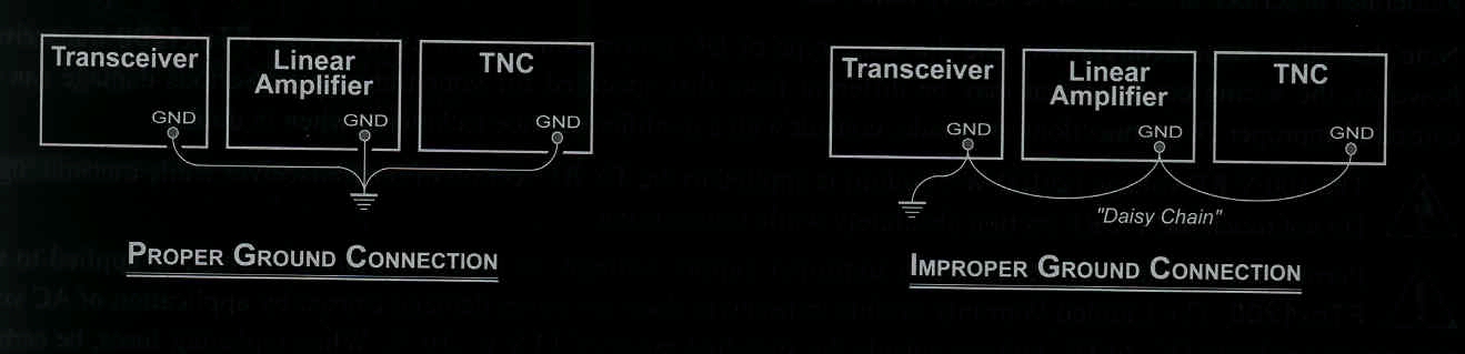
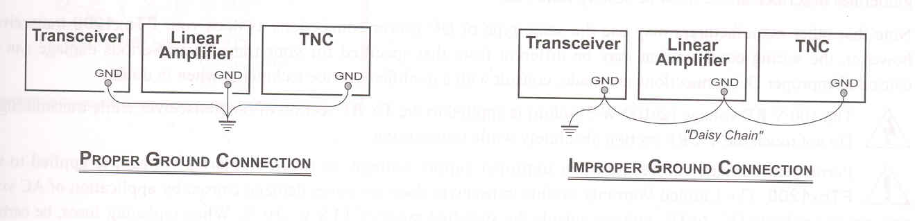
Inside the station, a common ground bus consisting of a copper pipe of at least 25mm diameter should be used. An alternative station ground bus may consist of a wide copper plate (single-sided circuit board material is ideal) secured to the bottom of the operating desk. Grounding connections from individual transceivers, power supplies, and data communications devices (TNC's etc.) should be made directly to the ground bus using a heavy, braided cable.
Do not "Daisy-Chain" ground connections from one electrical device to another and thence to the ground bus. This method may mulify any attempt at effective radio frequency grounding. See the drawing below for examples of proper grounding techniques.
Inspect the ground system - inside the station as well as outside - on a regular basis to ensure continued performance and safety.
Besides following the above guidelines carefully, note that household or industrial gas lines must never be used in an attempt to establish an electrical ground. Cold water pipes may, in some instances, help in the grounding effort, but gas lines represent a significant explosion hazard, and must never be used.
| Page 9 | FTDX1200 Operating Manual |